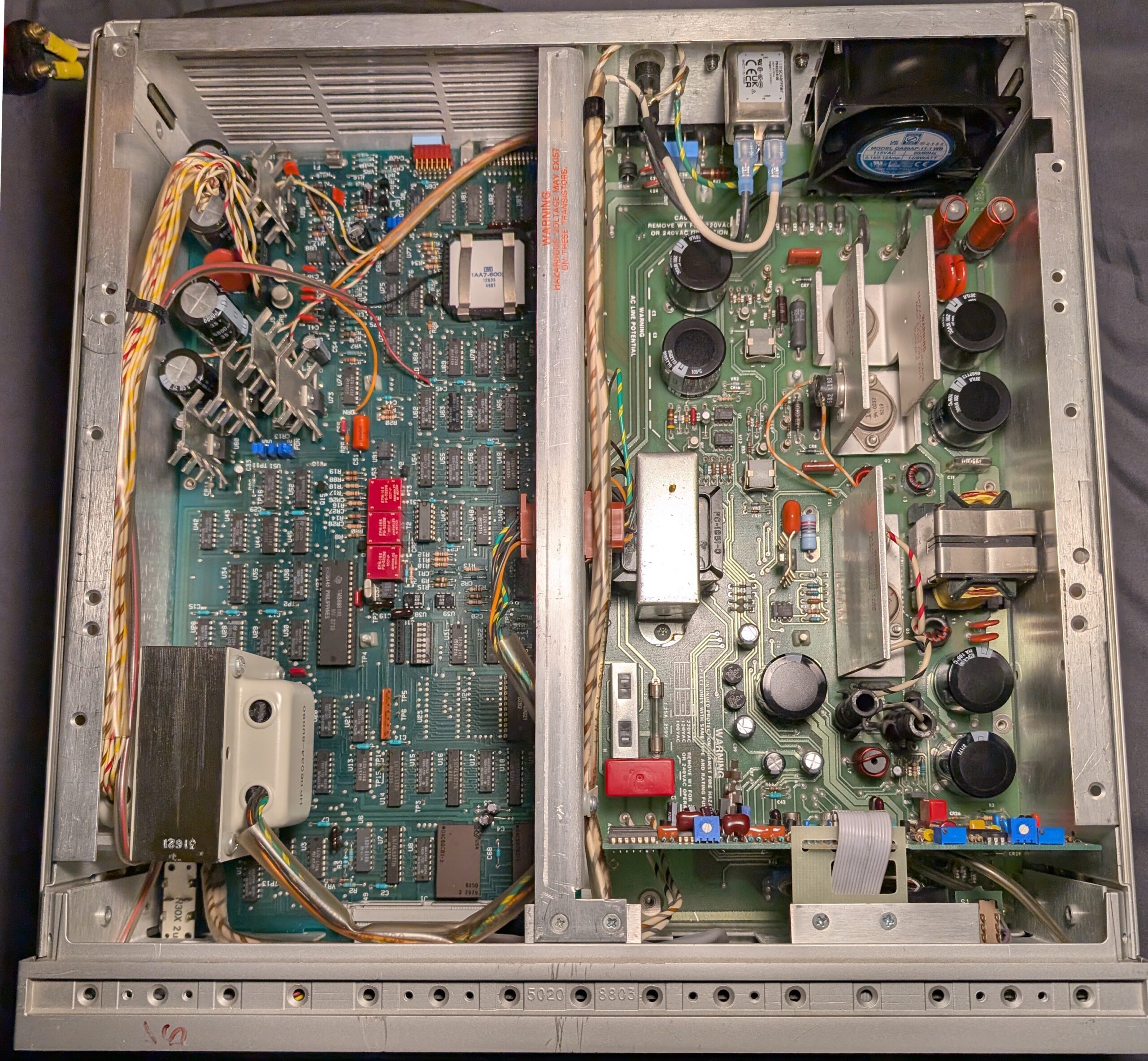
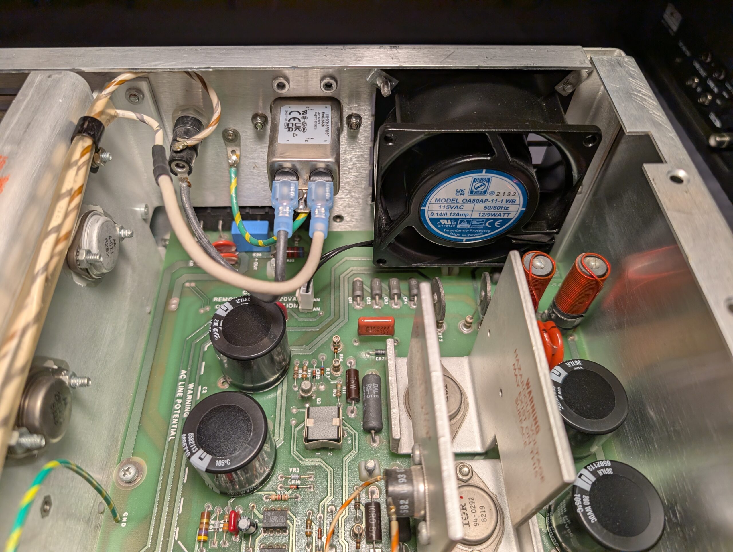
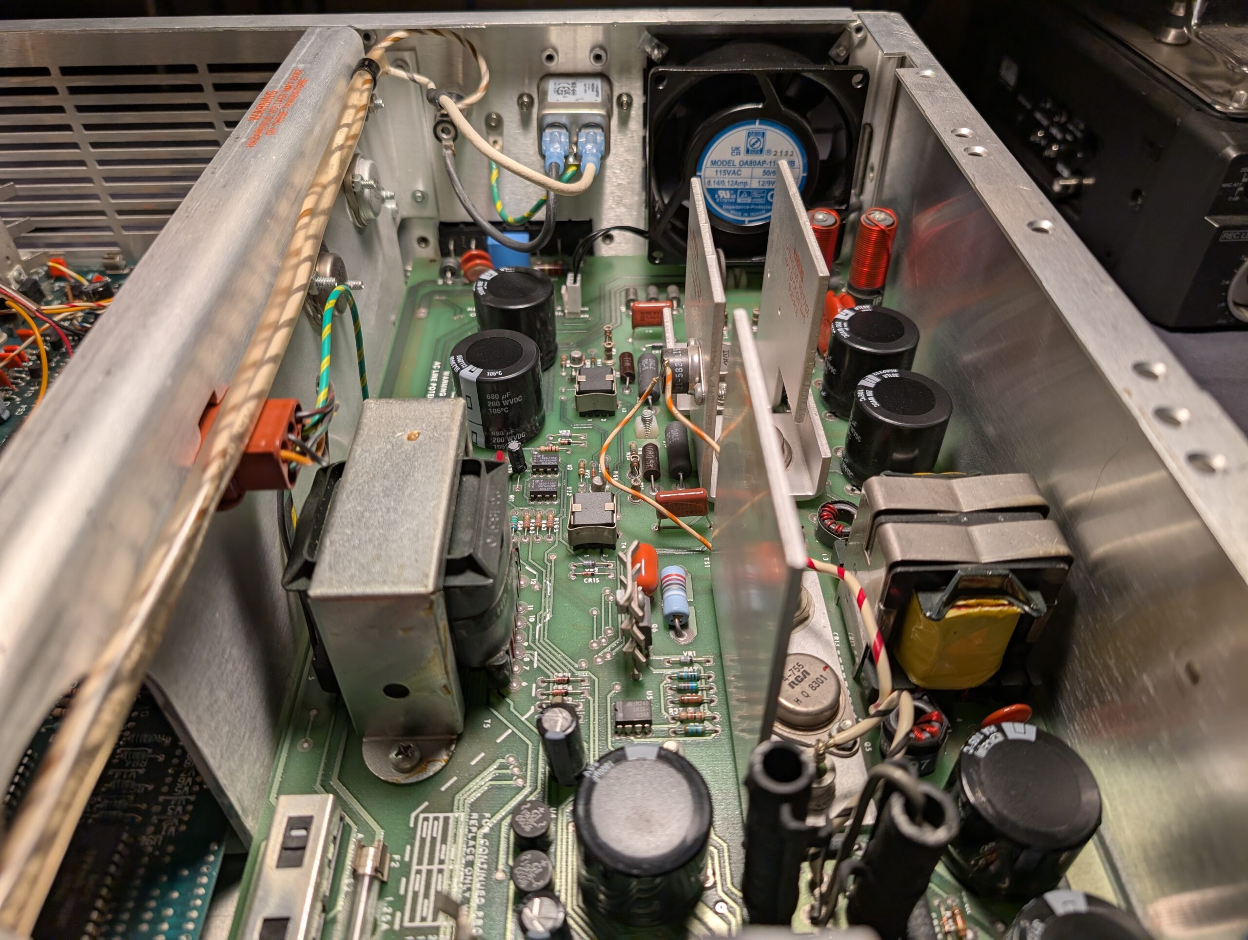
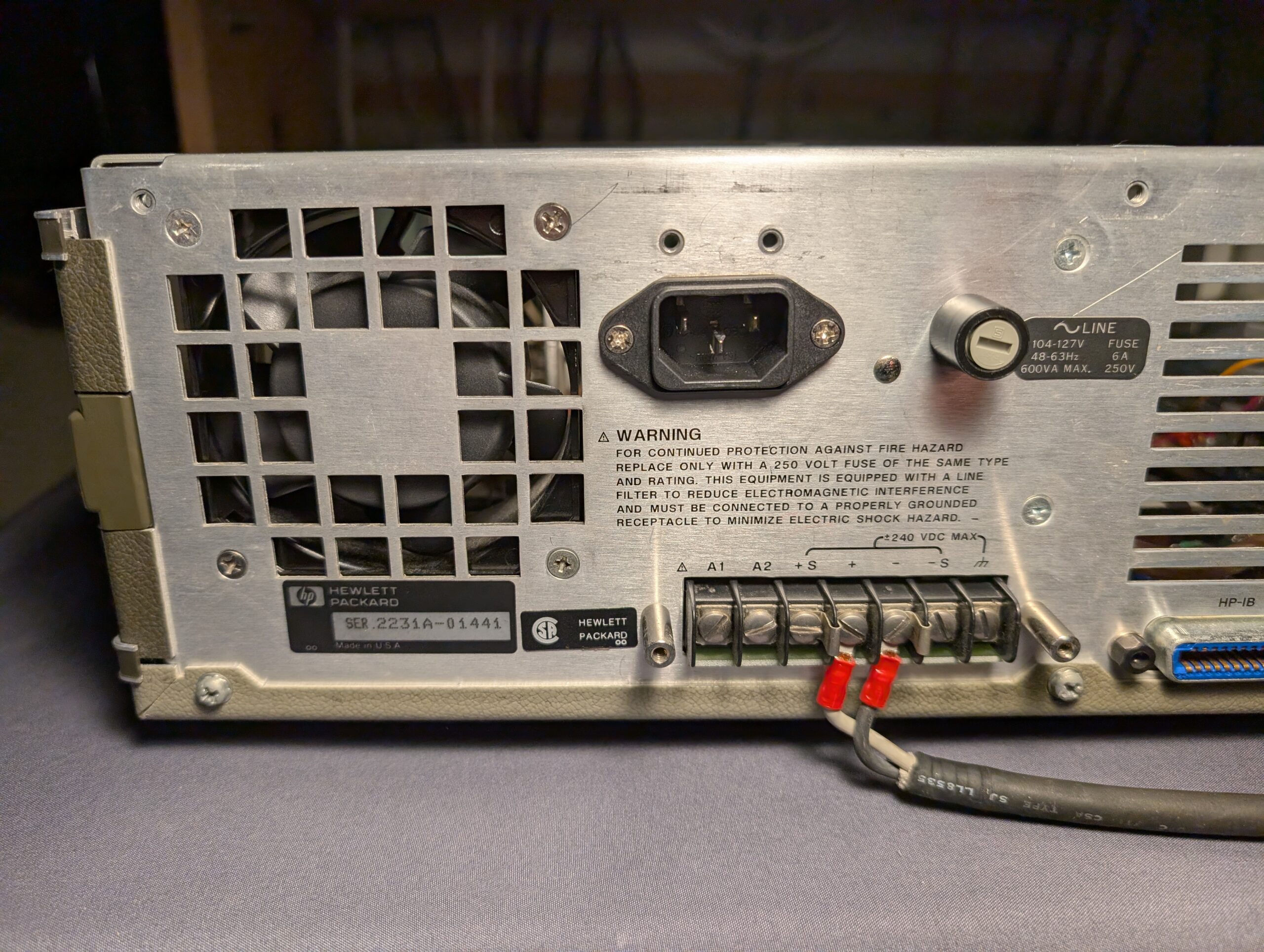
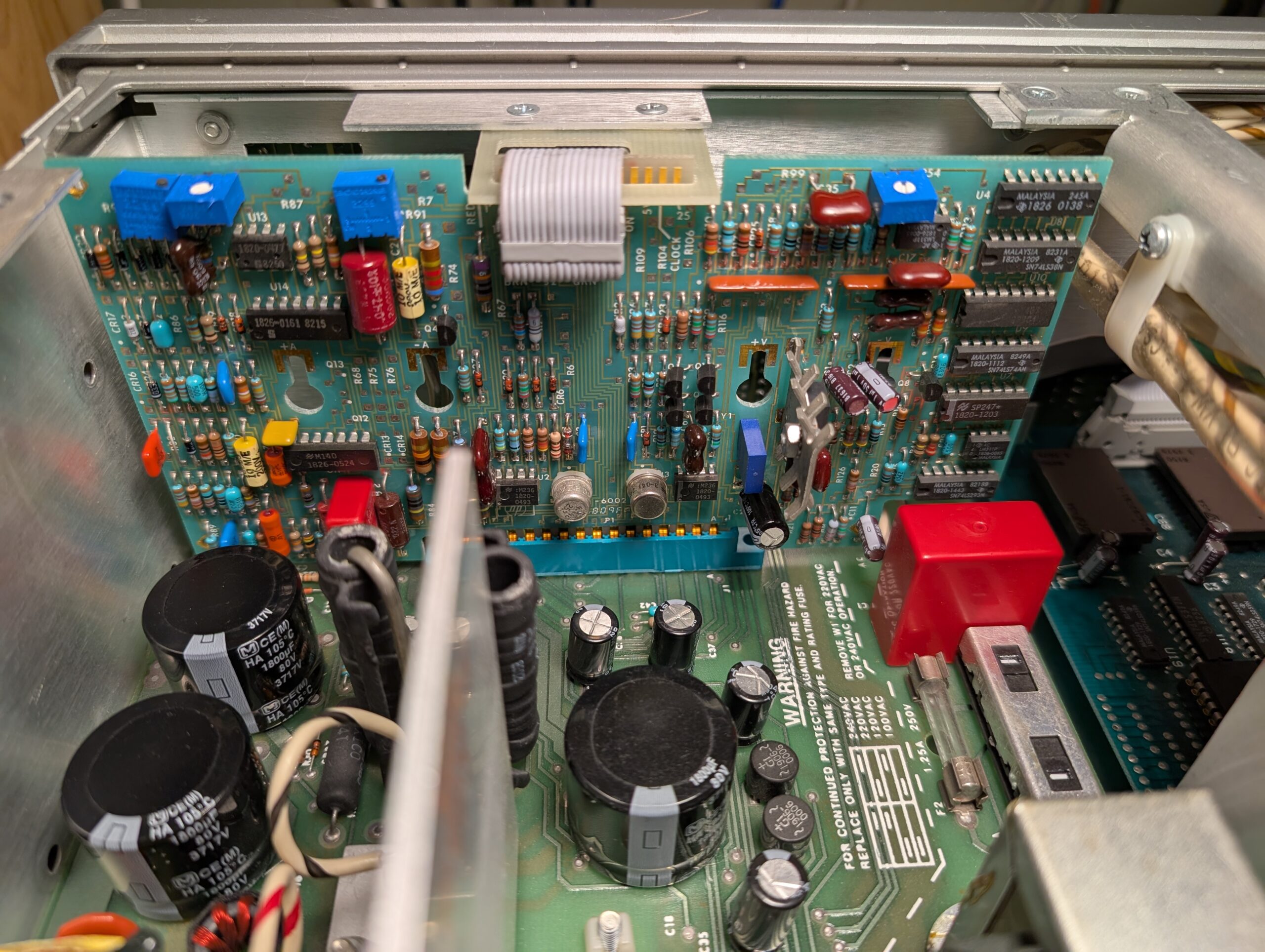
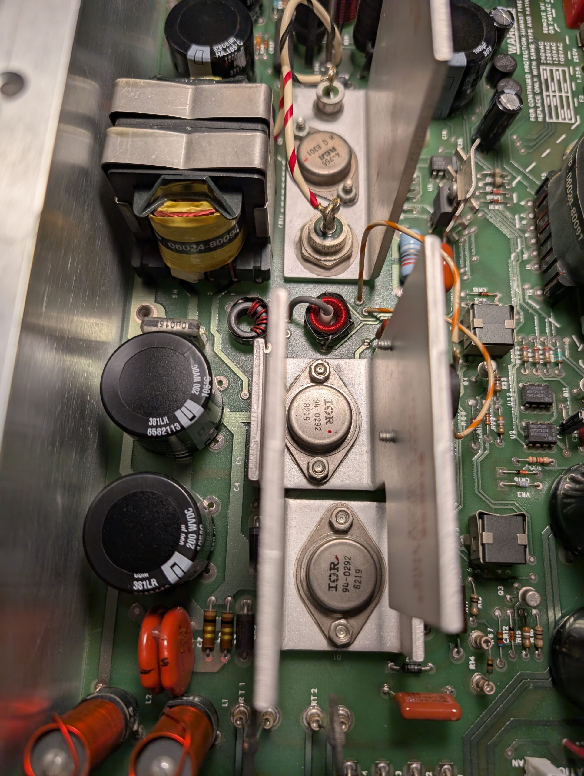
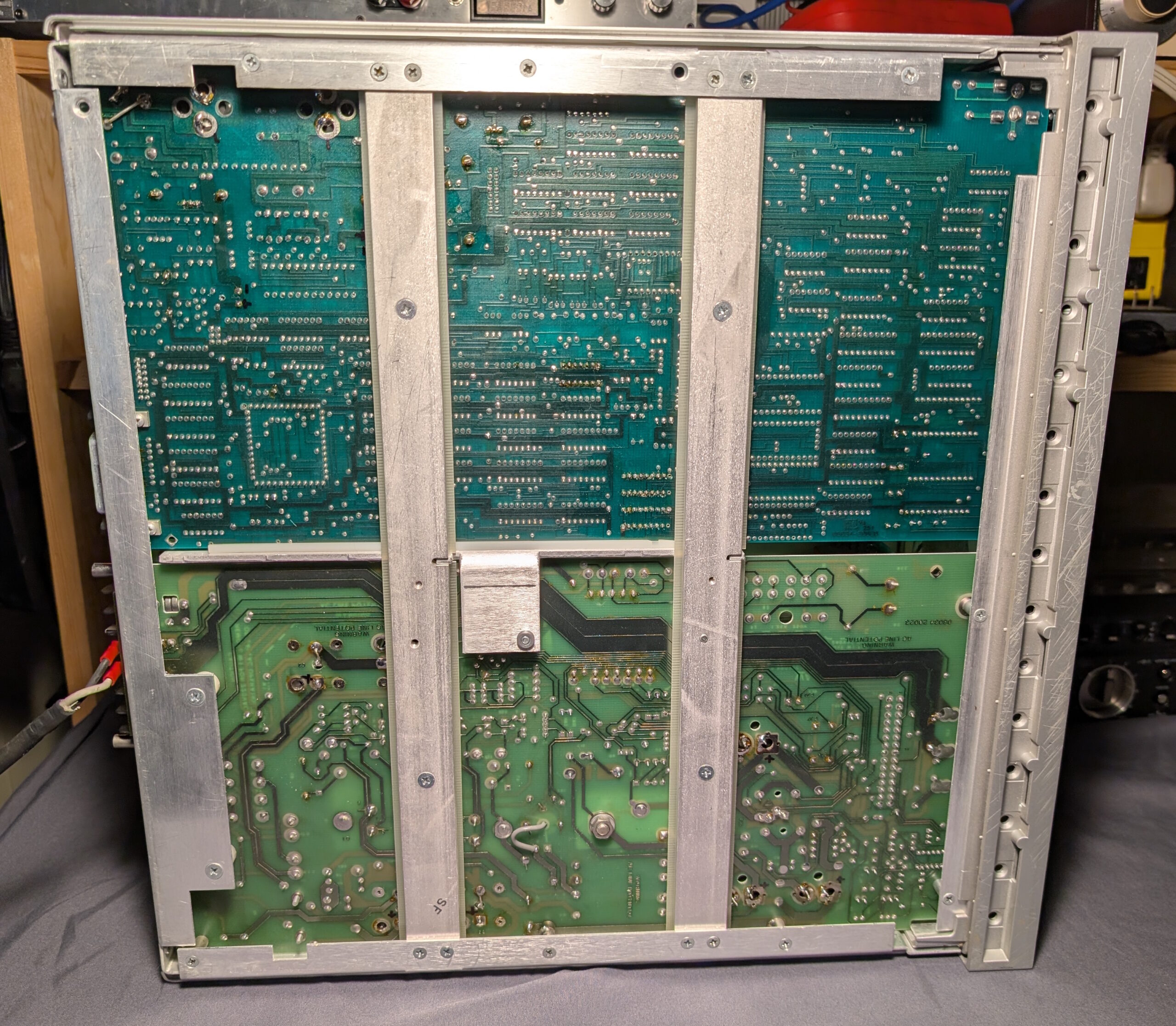
I scored this power supply a number of years ago on eBay for around $140 CAD which seemed like a deal at the time. The seller stated and showed in photos that upon powering up, all the front panel LEDs and display segments would light up and the unit would not respond to input. The voltage and current couldn’t be set, and assumingly the HP-IB would not work but that was never tested.
From what I can find, these power supplies had an MSRP of $2700 USD in 1983 which equates to about $7500 today (2024)! In practice this unit would have been part of an automated test setup utilizing the HP-IB interface in conjunction with various other pieces of test equipment for analyzing and testing electronic components and designs. It was never really intended for bench use, which is a reason I had purchased it.
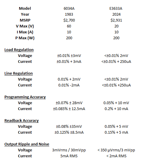
Below are some of the specs for this power supply, as well as a comparison to what I would possibly call its modern equivalent; the Agilent/Keysight/HP E3633A 200W bench supply which retails for about $3000. Considering the age of the 6034A and just how much discrete early 80s logic was required to make this thing work, I think it holds its own pretty well.

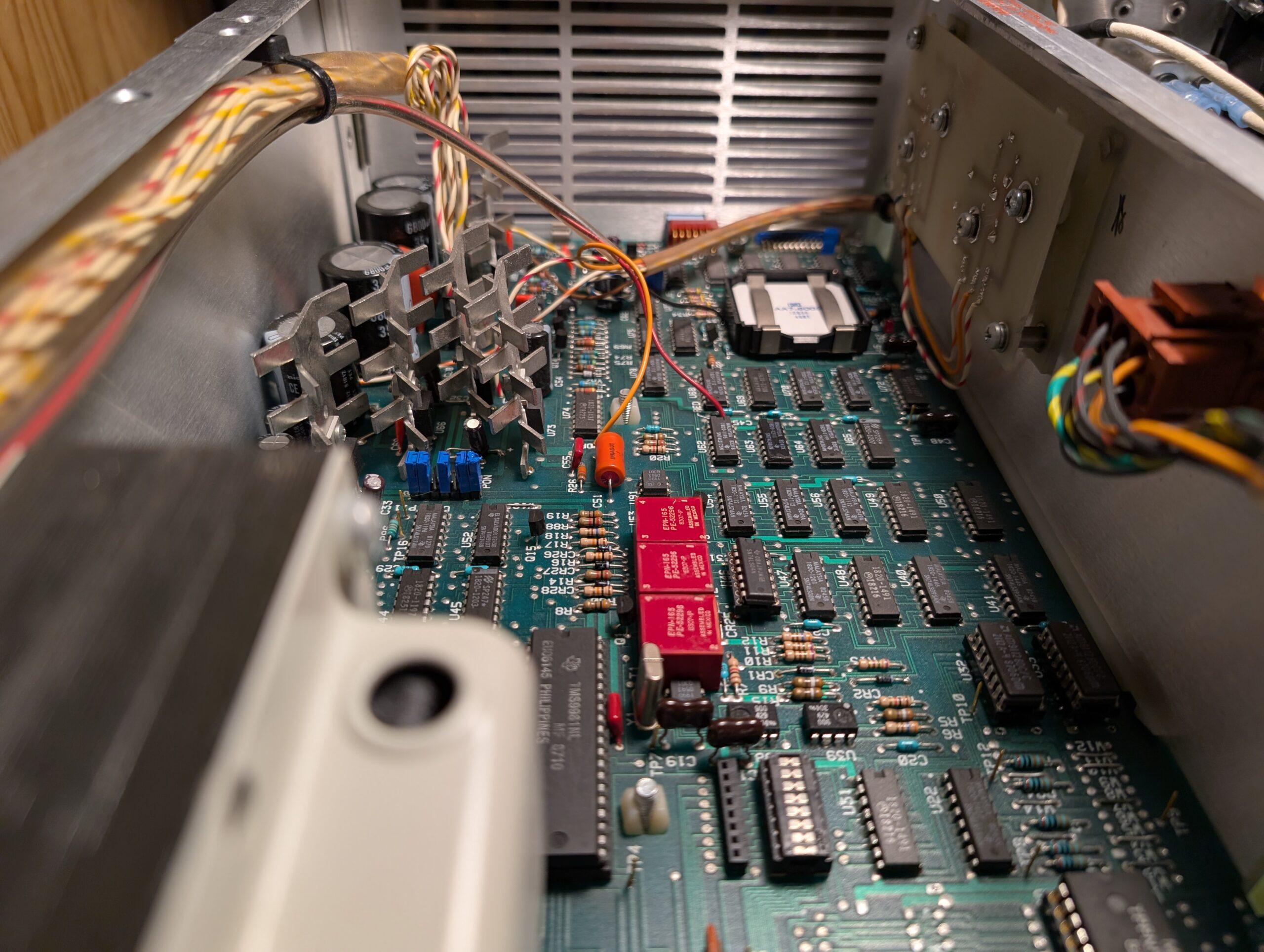
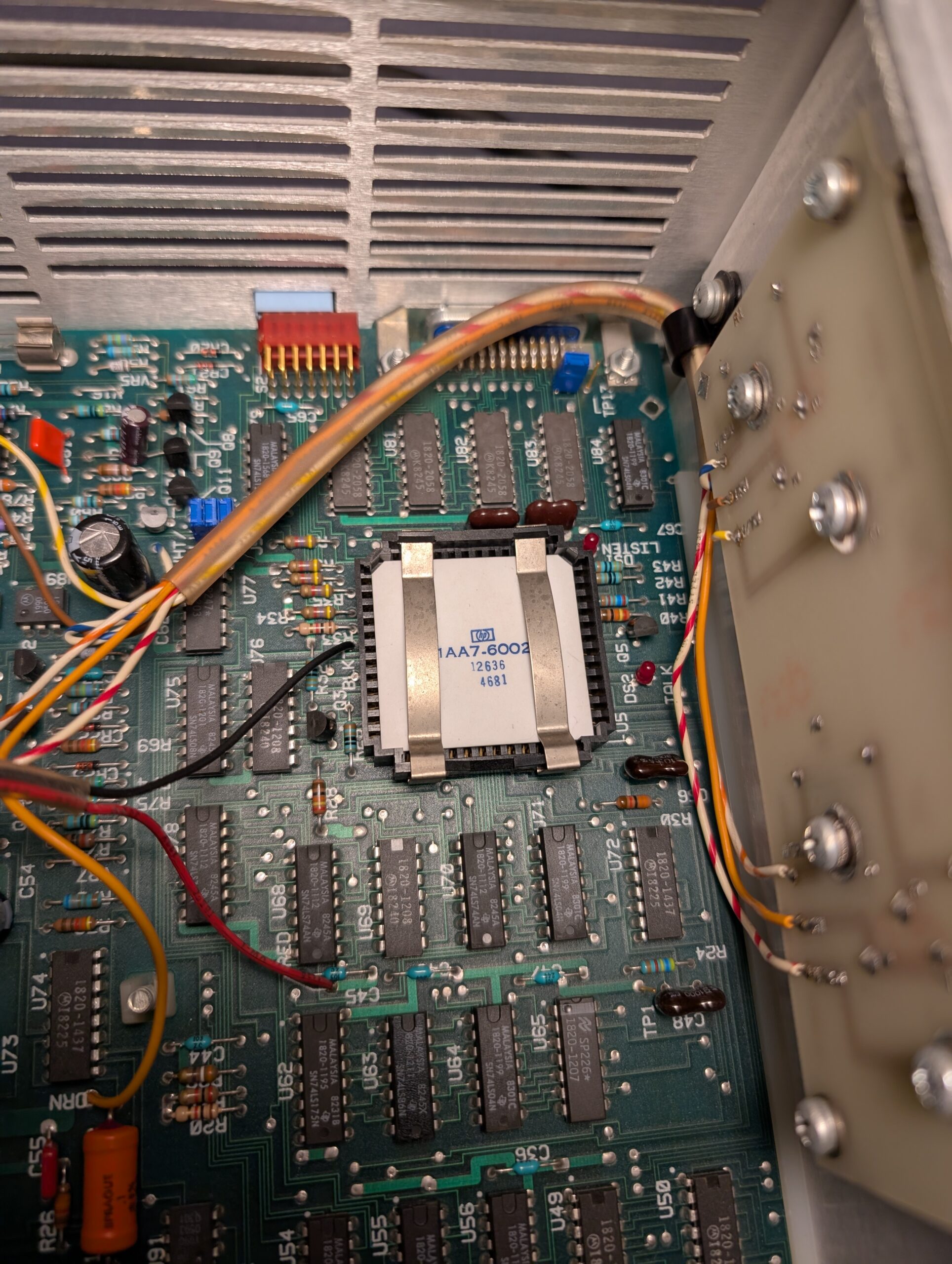
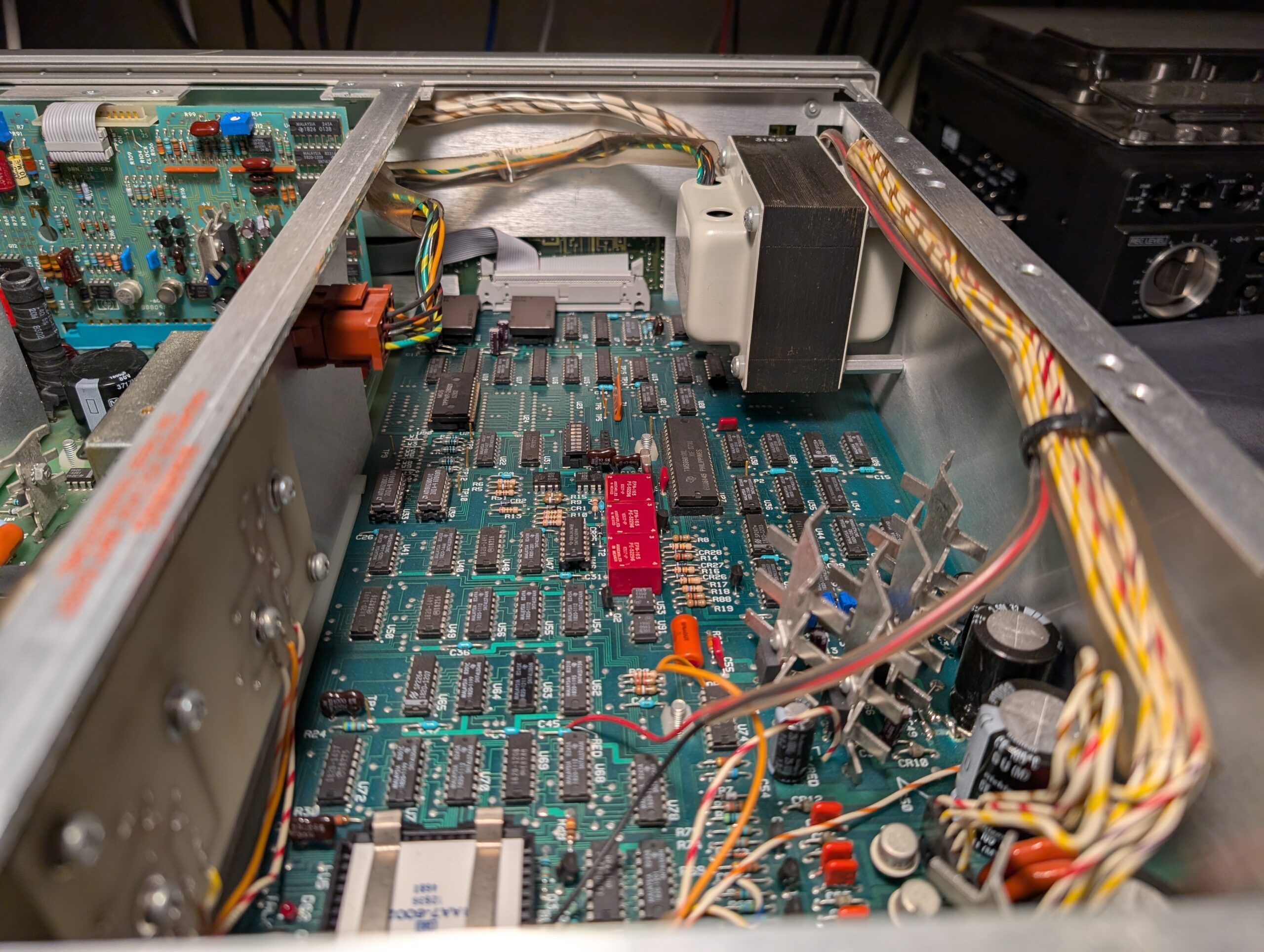
I had done a little reading on these and it sounded like a possible failure point was the CPU; a 40-pin 16-bit Texas Instruments TMS9981 with an 8-bit data bus. According to users online, it’s possible the chip itself is bad or simply making bad contact in the socket. Upon receiving the unit I powered it up and snapped the photos below:
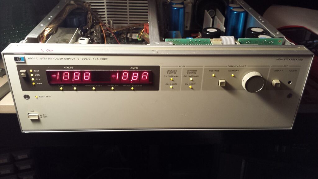


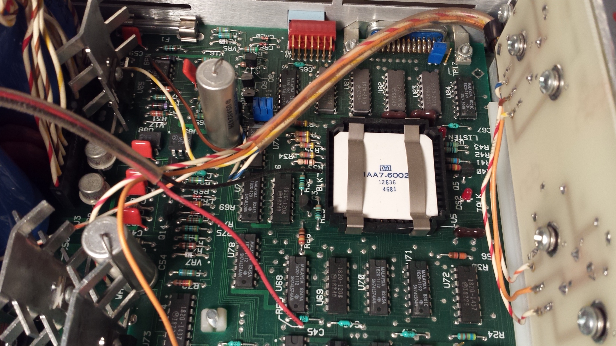


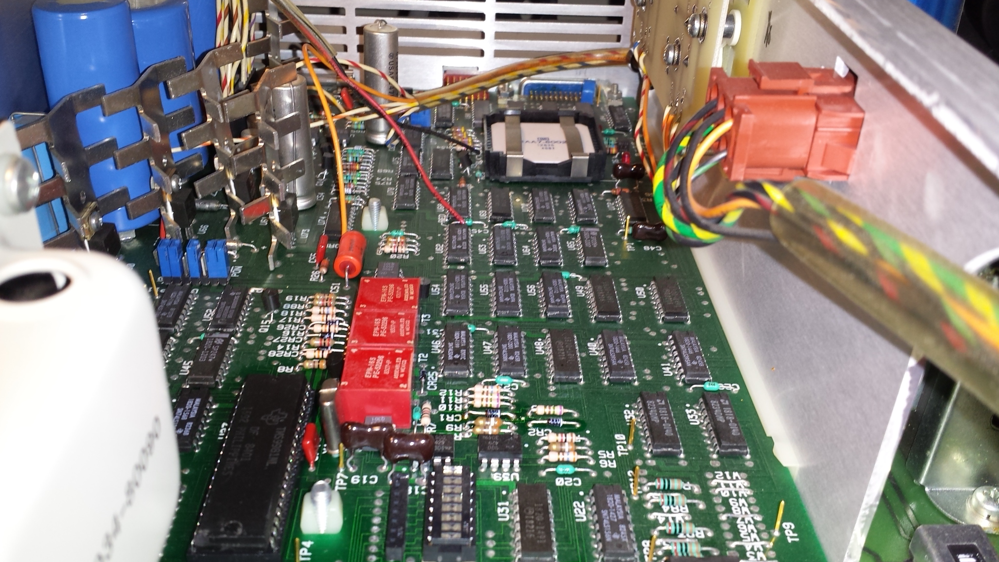


The seller was not lying – it was doing exactly as described. Unfortunately for me, the seller included two other TMS9981 chips which means they probably knew about the CPU issues. Dang. I swapped them out anyways just to see what would happen and to no surprise that did not fix the issue. What are the chances all three chips were bad? Probably very low but I moved on with troubleshooting.
The service manual is readily available and is extremely comprehensive which is typical of this era. It has all the schematics, block diagrams, circuit descriptions and troubleshooting flow charts you could ever want. It’s very helpful but also a bit overwhelming for someone who was more or less just getting into more advanced electronics repairs so I spent a fair bit of time browsing through it and trying to understand what was happening and where a fault might be. One thing that became clear was that the CPU was not booting up which led me to the incorrect assumption that something must be wrong with the digital logic side.
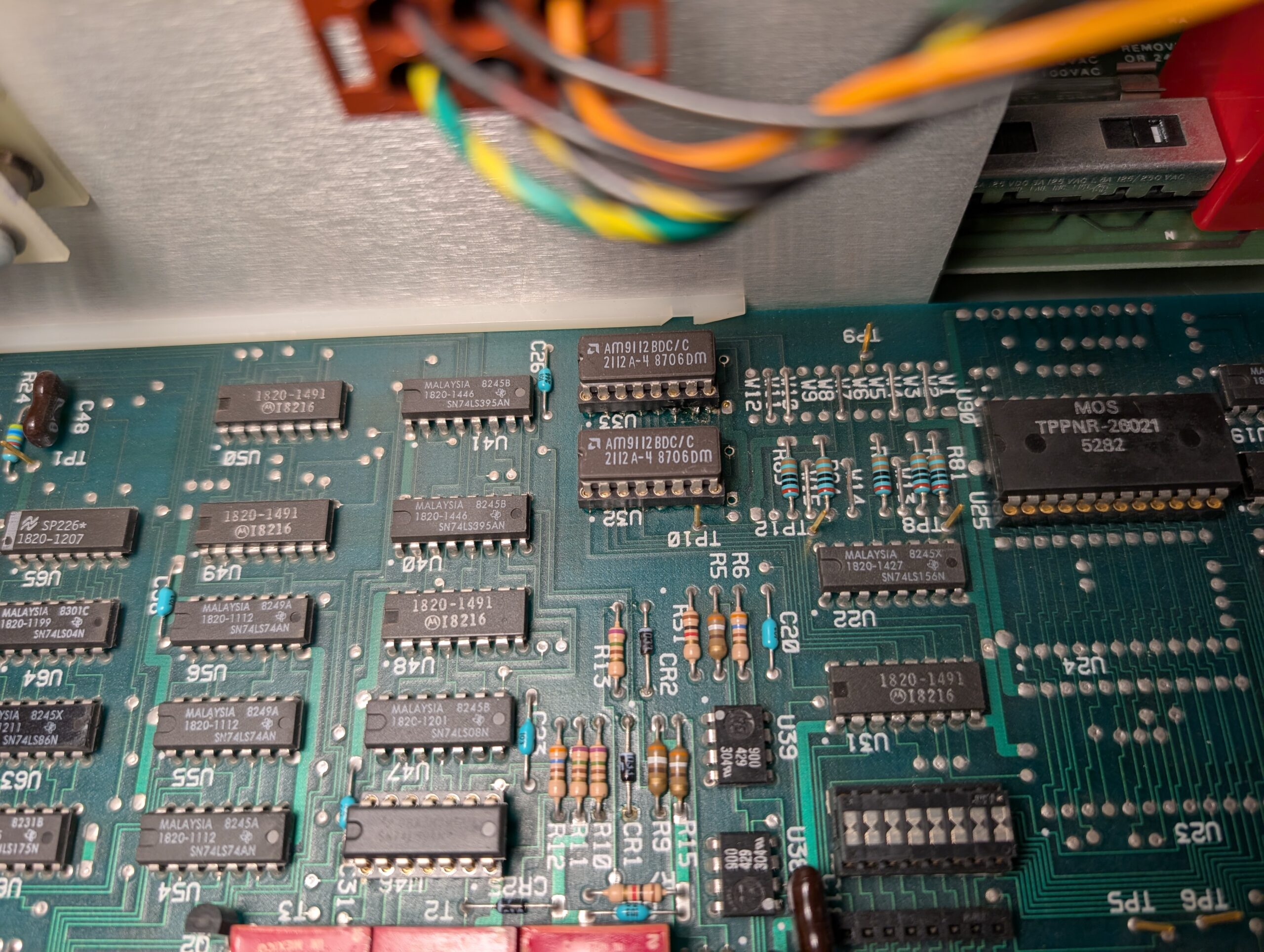
Due to this assumption I went on some goose chase with the EEPROM, making an adapter and programming a new one with code someone had uploaded to the EEVBlog forum. This too did not fix the issue. I replaced and socketed both the RAM chips, a whopping 256×4 bit (128 bytes!) AM9112 chips which did not fix it but did give me a problem later.
At some point I was probing the interrupt pins of the microprocessor and noticed the signals at INT1 and INT2 cycling around120Hz which seemed suspicious since that’s exactly the frequency you’d expect at the output of an unfiltered full wave bridge rectifier. Tracing the interrupts back led to U52, an 8-to-3 decoder, in this case an SN74LS148. The same 120Hz signal was found on pin 4, which itself was fed by U51, a hex D-type Flip-Flop SN74LS174N. The input to the flip-flop causing the 120Hz signal was a net labeled !PON2.
The service manual describes !PON2, along with !PON1 as being active while the unit powers up and powers down due to insufficient unregulated voltages for the digital logic bias supplies:

Below is the circuit which generates the !PON2 signal:
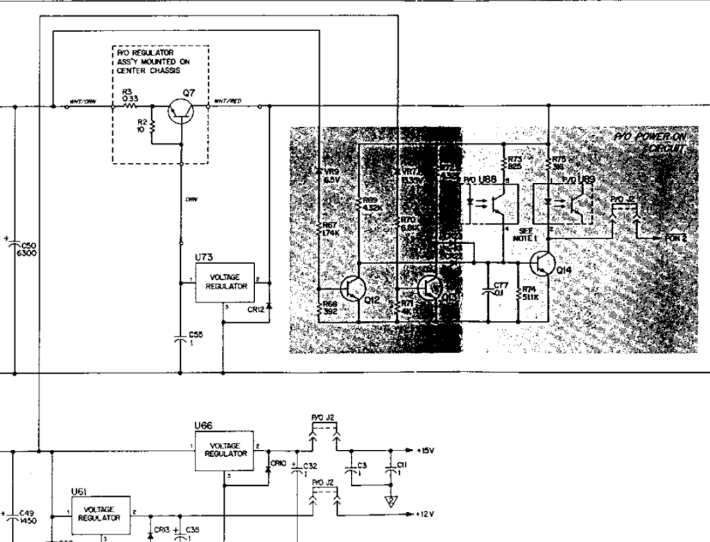
!PON2 is active low as long as Q14 is forward biased, which it is by default, from the 5V regulated output U73 and Q7. In order for Q14 to turn off, both Q12 and Q13 must be turned on by the 5V unregulated supply in addition to the +15V unregulated supply respectively. It’s hard to see in the schematic but there are two diodes, each coming off the collectors of Q12 and Q13 connected to the base of Q14 resulting in an analog AND circuit.
The +5V rail had already been confirmed to be working within some tolerance, so the culprit had to be the +15V unregulated supply side. And sure enough it was! The +15V rail was behaving like a 120Hz rectified AC signal with no DC filtering whatsoever meaning that some capacitor had gone to HP heaven.
Take note here, all the IC swapping and backtracking from the microprocessor back to !PON2 could have been avoided if I had simply checked all the power rails from the get go. Whoops! Always start with the easiest solution and work your way down.
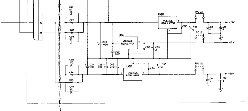
The only capacitor it could be is C49, which I removed and tested, and there was not a micro farad to be found inside. What should have been 1450uF was reading in the picofarad range, as was its counterpart C57 (not shown). At this point I decided to recap the whole unit because it was old enough to warrant it and something like this deserves fresh capacitors.
I won’t go into great detail but recapping was somewhat difficult as many of the original capacitors were screw lug or many-legged beasts with unusual pinouts. And just because I can I also replaced the +12V, +-15 and +5 regulators with equal or better graded replacements, and went ahead and re-applied the crusty old thermal paste to the heatsinks. I also replaced a number of capacitors on the mains side, such as C8, C9, C11 and C15 with appropriate safety caps where applicable. Lastly I replaced the fan with an equivalent (no silent mods), and the mains EMI filter and power input assembly due to the age of the components inside.
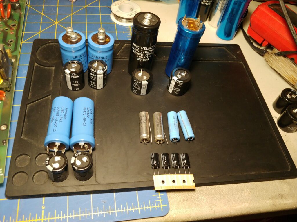
Eventually, with much delay and procrastination, I had all of the caps and hardware replaced and re-assembled it enough to test it. I had verified the polarities of the oddball capacitors several times in fear of having them explode during power on. Explode they did not when I finally powered it on, but unfortunately something was still wrong as the segments and LEDs were once again illuminated. But this time there was hope!

At first glance it appears we’re back to square one. But if you notice not all the front panel indicator LED’s are illuminated this time. With the original fault, the +15V rail an unfiltered rectified AC signal, the power supply was essentially resetting 120 times per second, but now with the new caps (and those AM9112 RAM chips), it showed signs of progress. I consulted the service manual again:
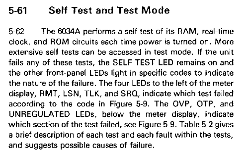
As it states, the SELF TEST LED remains on if a fault is detected while testing RAM, ROM or RTC. Several other indicators together display a failure code which narrows down the fault. In the previous photo, the leftmost-bottom LED is the self-test LED and is in fact illuminated and there is an error code which can be decoded with the next helpful diagram:
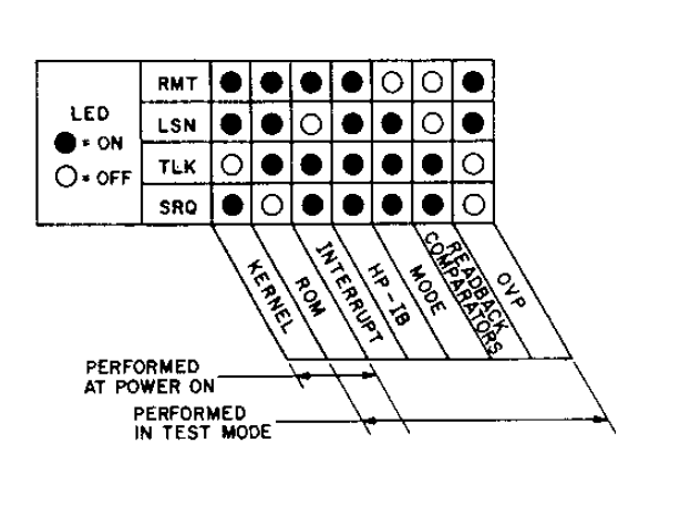
The leftmost-upper column of LEDs clearly show a Kernel fault of some kind. Further decoding is needed!

Narrowing it down ever further, it can be seem that our unit displays Fault Number 2. Excellent! Now what is fault number 2? Below is a snippet showing an explanation of some error faults:
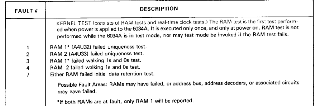
“RAM 2 (A4U33) failed uniqueness test.” I’m not entirely sure what a uniqueness test is, but it possibly involves writing to and reading back every address with data which it seemingly is failing to accomplish. Both RAM 1 and 2 we’re replaced and socketed in earlier troubleshooting attempts, so I decided to start checking the suspects. Eventually through probing with my multimeter I found that address line A7 was not making contact from the socket to the rest of the PCB. There was a small break in the fragile trace right near the pad which I went ahead and repaired.
After that repair the power supply’s micro processor successfully booted and the constant current and constant voltage controls were verified working. I ended up doing a rough calibration of the front readout and CC and CV controls and I am pleased with the end result. It is not the most user friendly bench supply as it was never intended to be used as one, with no option to enable/disable the output without turning the whole power supply on or off. The output connections are at the rear instead of the front and the controls are analog making it tedious to sweep up and down to the desired value, and setting the current limit or constant current must be done with the output shorted. That being said, it’s satisfying being able to utilize something so old and have confidence in the build quality and design to power decades more modern devices.
One final thought is that it might be an interesting project to make a sort of “head unit” which interfaces the HP-IB. A sort of breakout module with standardized banana plugs, the ability to precisely set the current and voltage digitally and a soft on/off of the output.