It is often useful to be able to test amplifiers or power supplies to see how they perform under their rated specs. This is often a challenge due to the excess amount of heat generated during these tests. One of the simplest and cheapest ways to create a dummy load would be to buy an electric heater and rewire it with some input jacks.
The heating element inside space heaters are made of nichrome wire which is an alloy of mostly nickel and chromium. It has a very high melting point, around 1,400C which makes it very useful as a heater coil.
The heater in question puts out 1500W of heat at 120V rms. The first thing to calculate is the resistance of the coil which can be found with the formula below:
\(P = \frac{V^2}{R}\)
\(R = \frac{V^2}{P}\)
\(R = \frac{120V^2}{1500W}\)
\(R = 9.6 \Omega\)
This heater has two coils around the perimeter connected in parallel giving us a total of \(19.2 \Omega\) per coil. Seeing as there are two, it would make sense to make a dual dummy load with multiple taps at \(16 \Omega\), \(8 \Omega\), \(4 \Omega\) and \(2 \Omega\).
Knowing that each coil dissipates 750W maximum, twice this value will be used as a maximum value to calculate how much power can be dissipated on each tap.
The power dissipated by the coil depends linearly on its length. Since the full 750W is dissipated over \(19.2 \Omega\), tapping half way at \(9.6 \Omega\) corresponds to 375W dissipation. Tapping a quarter way at at \(4.8 \Omega\)corresponds to 187.5W and so on. Below is a simple formula relating the resistance tap to maximum power dissipation:
\(P = 750W \times \frac{R}{19.2 \Omega} \)
\(P_{16 \Omega} = 625W \)
\(P_{8 \Omega} = 313W \)
\(P_{4 \Omega} = 156W \)
\(P_{2 \Omega} = 78W \)
Putting both sides in parallel allows for double the power dissipation if required.
Another benefit of having two sets of taps is that the source can be connected between any of the two taps instead of just one tap to a common point which gives the following additional resistances:
- 14
- 12
- 6
By putting both sides in series these are all the values achievable:
- 32
- 30
- 28
- 24
- 22
- 20
- 18
- 16
- 14
- 12
- 10
- 8
- 4
- 2
Or by putting each side in parallel we can get almost any value from 1 to 8 ohms to in ~0.2 ohm increments.
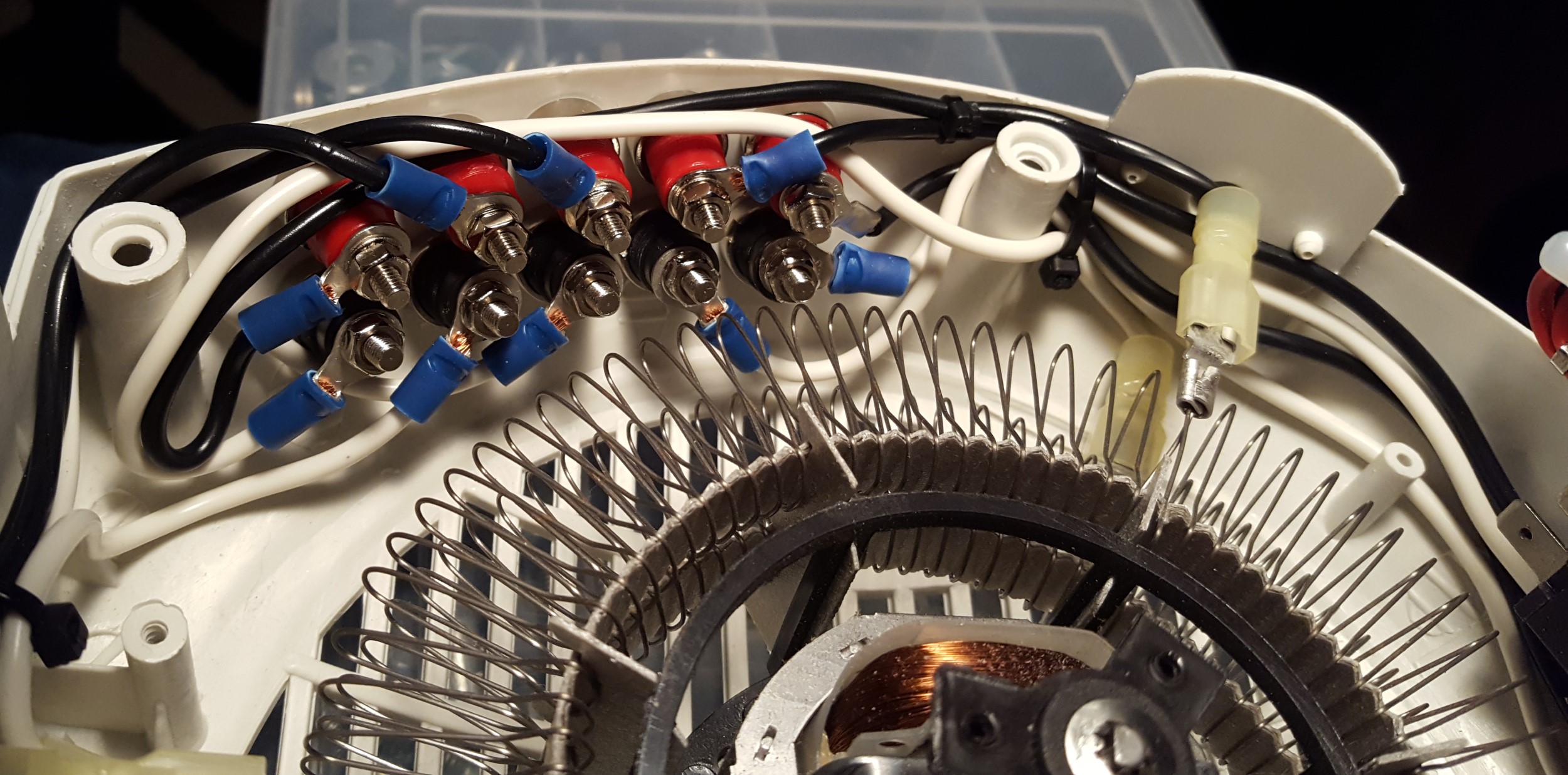
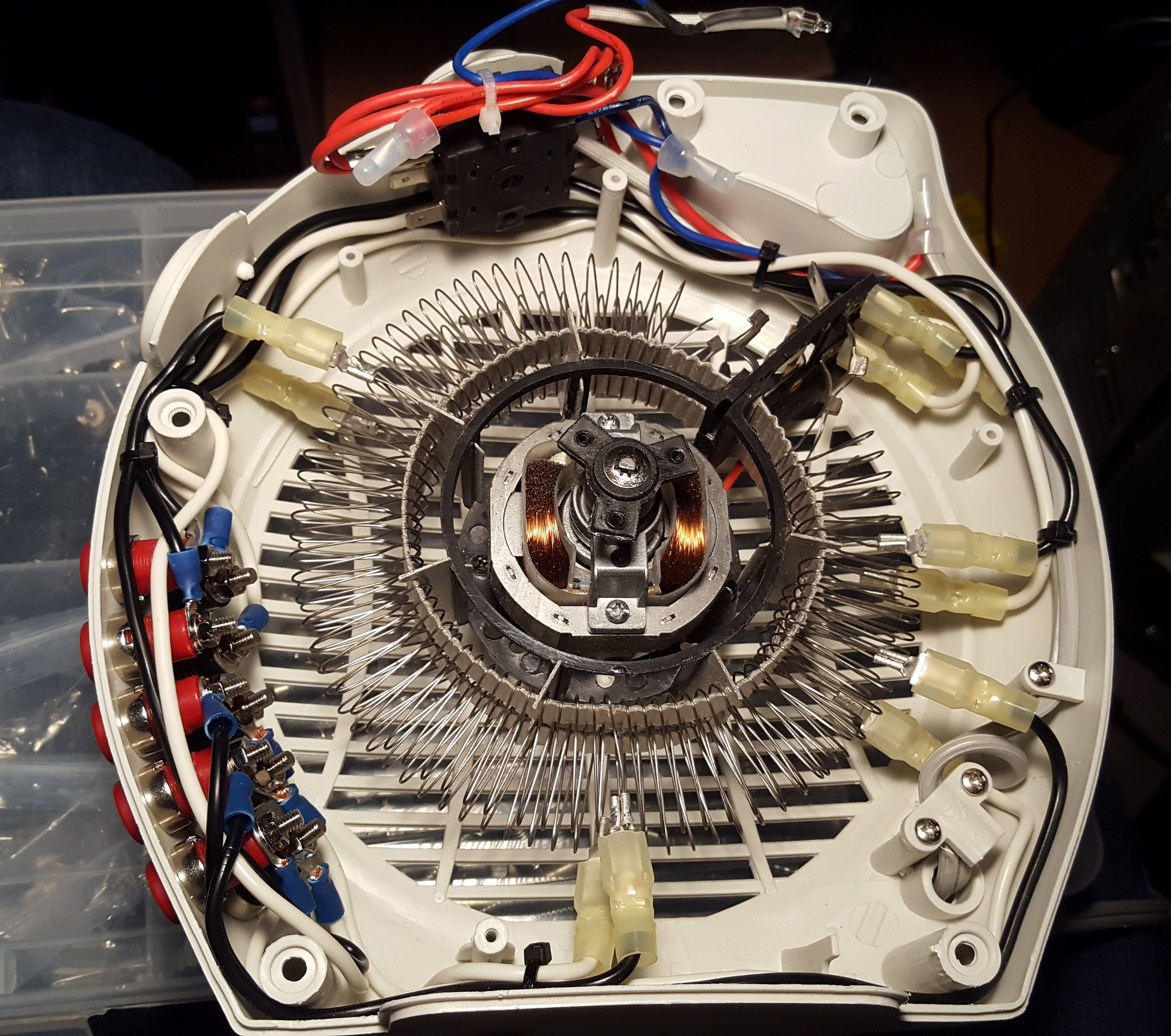
Lastly some images of the finished product. Knowing that the wire gets too hot to solder, all the connections were crimped and the wires routed to keep them as far from the coils as possible. The fan itself is hard-wired to mains meaning it starts running as soon as the unit is plugged in.
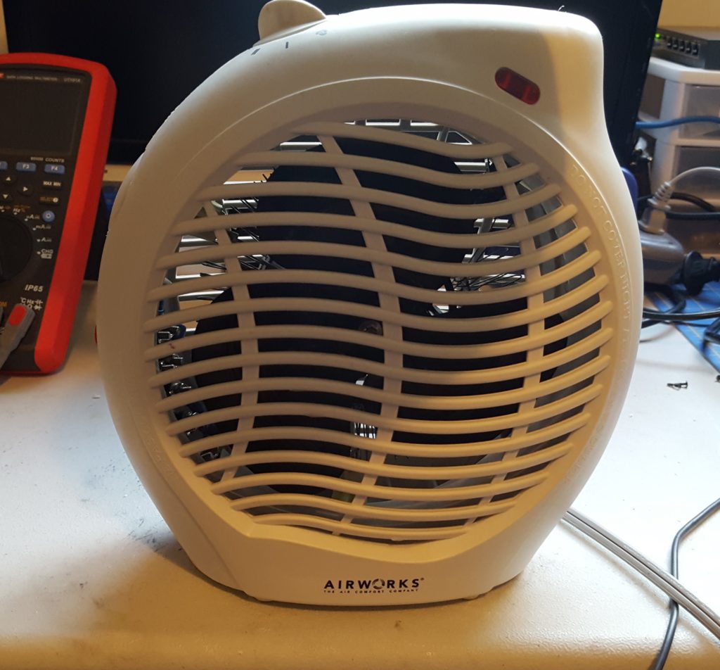
Front 
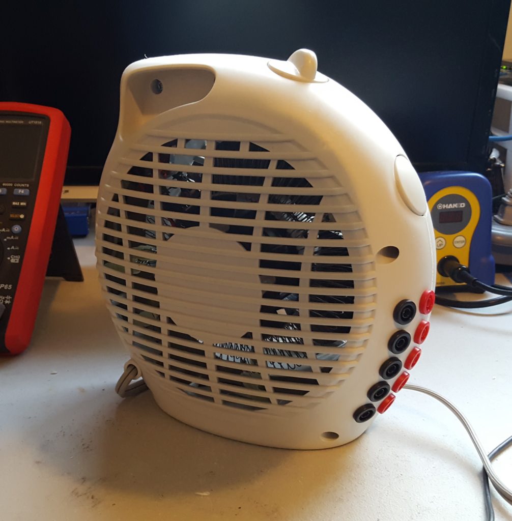
Rear 
Internal wiring


Hello again,
This is a really cool idea. I might look into doing this also. I have a few small electric heaters laying around. I’ve also considered making one with water heater elements in paint cans. Seen a few done like that.
What kinda inductance is there on those elements?
I have some mains rated thermistors that would work good for the fan. Only coming on when heated up.
Thanks again, Ken